Choo~Choo!
A Model Railroad? Really?
I had a Märklin HO starter set in the 1980s and remember being fascinated by the various train models in their catalogs, but everything was far outside of my budget then... and now—or so I thought! Turns out the Japanese N-gauge products are quite affordable even after import, well- relatively speaking, because it's still an expensive hobby compared to drawing, reading and writing, programming and collecting water bugs. It's arguably a bit cheaper than play-functional Warhammer 40K though, depending on what you have planned. It's much cheaper than something like semiprofessional cycling. We're talking 250-800 euro to build a small train layout with some interesting stops.
KATO and TOMIX seems to be the big model railroad brands. There's also Micro Ace and Greenmax. TOMIX (Tomitec) appeas to be a subsidiary of Takara Tomy of ZOIDS and '80s toy fame. Looking online, people seem to own more KATO than TOMIX. I bought mostly TOMIX stuff though (via amiami, or "oh-ami" as they're actually called), and now I'll blabber about my experience with this hobby as I dive in.
Packaging
The TOMIX and KATO loose cars and trains often come in boxes made out of thick clear plastic. These look overly sturdy, but the N-gauge models can be a bit fragile with their many fine plastic details like railings. I found the KATO box I got a bit more difficult to open. The TOMIX ones have little raised bumps on the corners to prevent scratching and ease stacking, but some of mine still had faint scratches. I only got one cardboard box (2770, Mitsubichi 1990 canter truck transport wagon*). The inserts vary from styrofoam, vacuformed plastic, to foam. One thing to look out for is "missing parts"—they're actually hiding in various secret compartments. Not all models come fully assembled, but have little serial numbers, turning wheels, handrails, greebles and extra decal sheets (though lettering is often pad-printed directly on the model).
( * This wagon came with water transfer decals. I used DecalFix to assist with adhesion. The text lines need to be cut very close to the text because the side of the car is very narrow. The trucks need to be painted a bit, mainly the headlights and some silver parts. )
I believe the larger sets of trains and wagons come in "books", i.e. something like a large DVD case, but with a foam insert for the models. These can be bought separately. It makes storing trains in a bookshelf easy, if space is too tight for display. A simple display can be done in a glass cabinet with the trains sitting on straight rail, like s280.
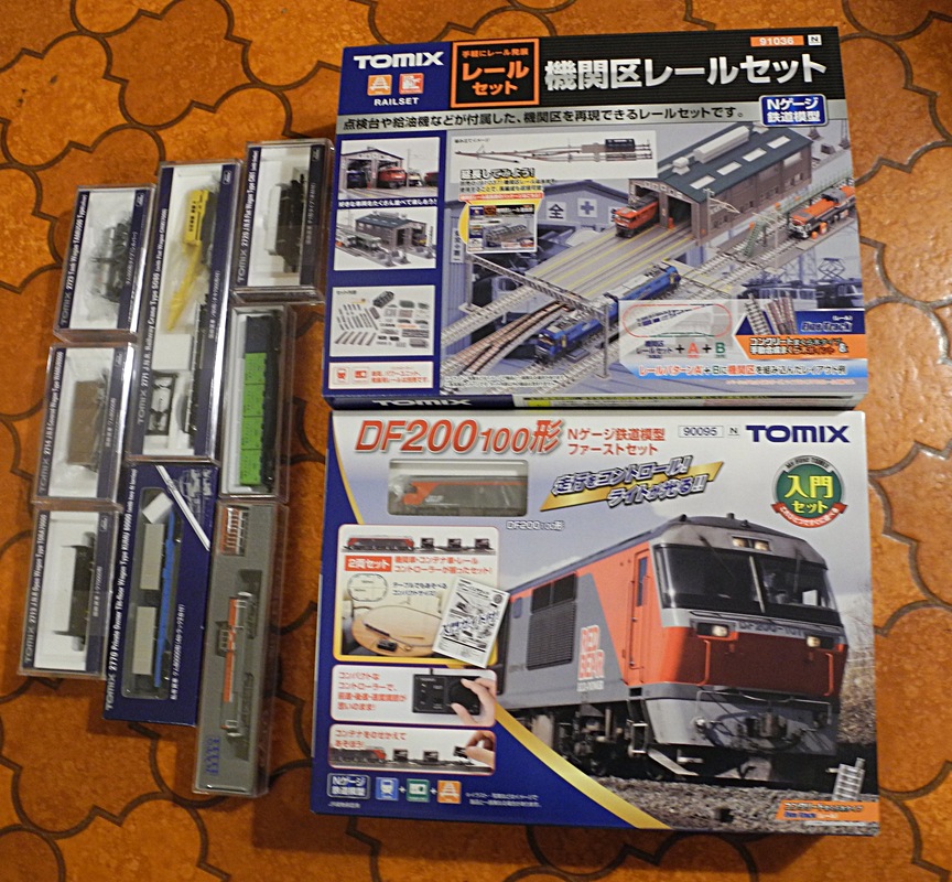 The starter set boxes are made from sturdy cardboard, with tightly stowed cardboard boxes and spacer inserts. The sprues come in plastic baggies. The track pieces were cleverly snapped on top of each other with clips, and smaller sections came joined into longer rail sections. The B&W instructions are in Japanese and it helps to know some Katakana and 100 basic Kanji, but the illustrations will help the beginner. The basic loop is very simple to set up. Complex railyards requires a bit more thought because of the way the power is switched around.
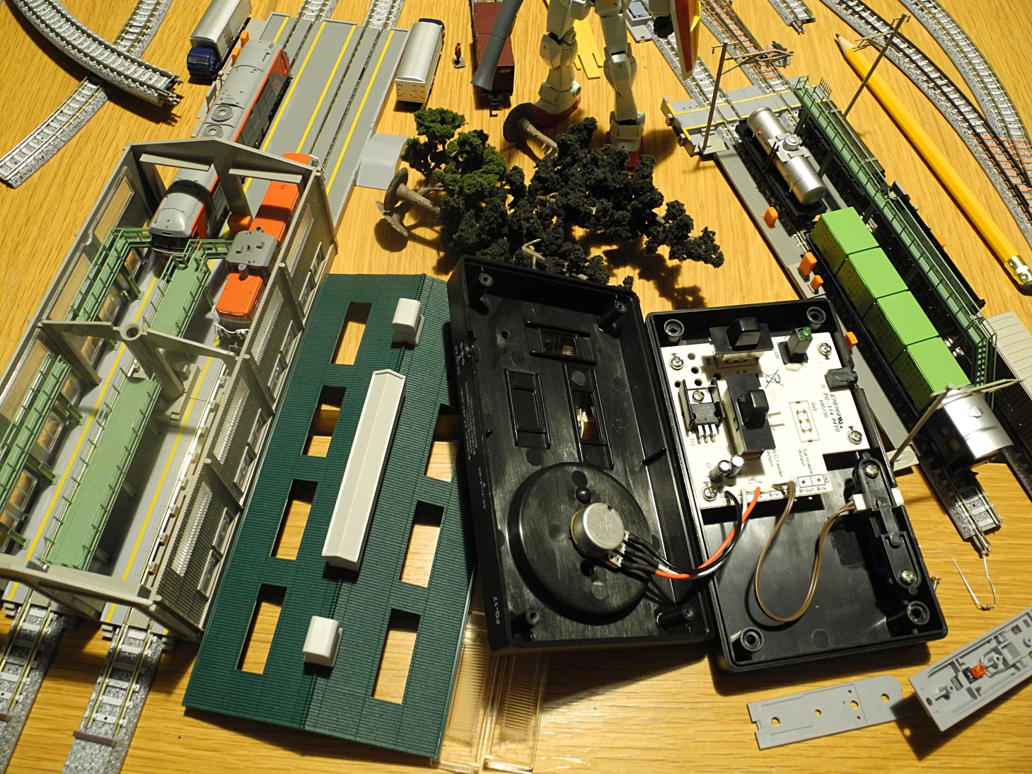 I bought this rather expensive parking garage with a small railyard around it. I figured that when you set up a naked loop on a table it will look quite boring. Some buildings and trees will help immersion. But I guess I'll have to build a proper diorama on a wooden board for it to work best.
TOMIX Electricks
It appears that the plain DC power / control system is common in Japan. Basically, the trains are powered by using some technique to vary the voltage on the rails, which makes the train motor go, also lighting up LEDs and such. The side track splits can be flipped manually or via momentarily powered coils (electromagnets).
The more complex DC setups rely on sensors that detect train positions and power up different isolated track parts and any trains on them. It needs a special controller and a thinking cap to get working. One way to avoid that is to use parallel tracks to create the illusion of more action, rather than wrestling with expensive special bits and polarity issues around switches. That stuff is not something for a beginner layout anyways.
One thing that people deep into the hobby apparently like to do is setting up huge railyards for parking all of their trains and shifting wagons around without cheating so the speak. Railyards are really just something for people with space... just imagine having multiple meter-long cargo trains which need to park in parallel. Also, one issue with complex rail yards is that they become more of a current puzzle than an actual simulation, kind of killing immersion if you ask me. In real life tracks don't have polarity, and on a model railroad you still need to unhook wagons by hand afaik. I plan to use manual switches for some occasional side tracks, and maybe a powered one or two for any automated stuff.
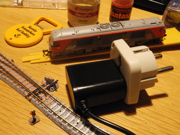 The power adapter can be used almost worldwide it appears. The back on my dinky cheap one says 100-240V 50/60Hz 0.3A AC to 12V DC 500mA (I measured 12.2V unloaded). It has the same form factor as the basic switchmode USB supplies used with phones, but it has a small center positive barrel jack. The passive plug adapter I used here is maybe an US one. It just changes the plug style—I don't need any change to the voltage in this case.
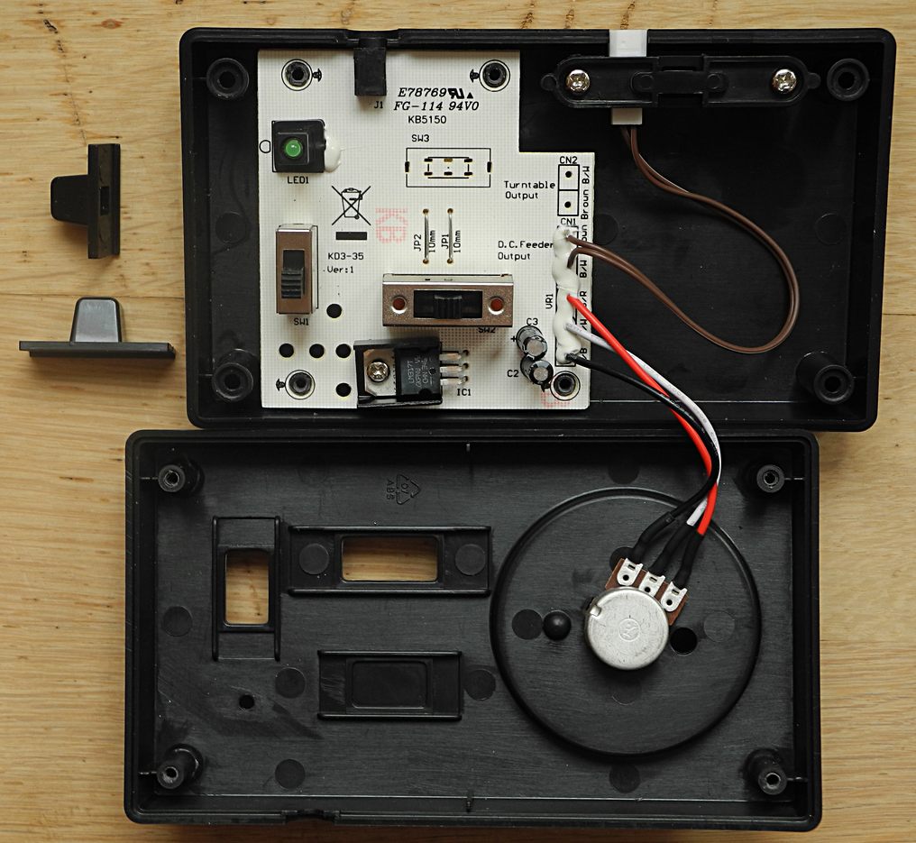 I opened up the little black controller in the TOMIX beginner set. Note the unpopulated turntable stuff and plastic bracket allowing for a second output (related to a "turntable").
The PCB looks very sturdy, somewhat like a PSU PCB, but didn't have much on the topside. An LM317T adjustable regulator (LDO) is used in conjunction with a (1K?) potentiometer (on the adjust pin). This regulator is sometimes used in simple DIY bench power supplies. The LM317K can output 1.25V to 37V out of 40V in, but since we have 12V in the situation is different. Strangely I saw 5.6V minimum to 12V maximum on the rails, which contradicted the back of the controller, which says DC 0-8V 300mA max. Then I discovered that it varies by load. With a train on the track I get the correct voltages. I wonder if a LED works as a load (the LM317 has a "minimum load" figure of a few mA)... The load of a motor is massive in comparison—or so I thought! The N-gauge train motors are quite small and not like the typical hobby motor.
Curious, I powered up a separate rail bit and jumped the power over to the main loop with my multimeter (set to Ampere measuring mode) sitting in between (series). Here are the measurements for the TOMIX DF200 pulling three industrial wagons:
Minimal crawl: 0.06A / 60mA (1.7V)
Mid speed: 0.09A / 90mA (4.5V)
Max speed: 0.120A / 120mA (8V)
The figures drop slightly by distance from power source due to rail resistance. Because the controller has a 300mA supply limit, there's some margin for additional stuff. I don't know how much power the switch point coils draw... I think they should be momentary bistable (unlike e.g. a held pinball flipper).
The trains don't move at lower voltages—the turn knob needs to go over 1.7V or so, making 4/22th of the speed wheel a bit limp (LEDs might only come on at 1.7V or higher too). The speed indicator print should've had a marking that indicated crawl I think, but the crawl point likely varies by train model. I added one myself after thinking about this.
The direction switch has three states: Left, Stop and Right (what's forward and back is unknown as the trains can be put on the track facing either way). The switch is just a multi-pin sliding switch that flips the polarity on the rails or leaves them unconnected. In a real train (of an older model) direction is more likely set by a turning handle.
I opened up the little black controller in the TOMIX beginner set. Note the unpopulated turntable stuff and plastic bracket allowing for a second output (related to a "turntable").
The PCB looks very sturdy, somewhat like a PSU PCB, but didn't have much on the topside. An LM317T adjustable regulator (LDO) is used in conjunction with a (1K?) potentiometer (on the adjust pin). This regulator is sometimes used in simple DIY bench power supplies. The LM317K can output 1.25V to 37V out of 40V in, but since we have 12V in the situation is different. Strangely I saw 5.6V minimum to 12V maximum on the rails, which contradicted the back of the controller, which says DC 0-8V 300mA max. Then I discovered that it varies by load. With a train on the track I get the correct voltages. I wonder if a LED works as a load (the LM317 has a "minimum load" figure of a few mA)... The load of a motor is massive in comparison—or so I thought! The N-gauge train motors are quite small and not like the typical hobby motor.
Curious, I powered up a separate rail bit and jumped the power over to the main loop with my multimeter (set to Ampere measuring mode) sitting in between (series). Here are the measurements for the TOMIX DF200 pulling three industrial wagons:
Minimal crawl: 0.06A / 60mA (1.7V)
Mid speed: 0.09A / 90mA (4.5V)
Max speed: 0.120A / 120mA (8V)
The figures drop slightly by distance from power source due to rail resistance. Because the controller has a 300mA supply limit, there's some margin for additional stuff. I don't know how much power the switch point coils draw... I think they should be momentary bistable (unlike e.g. a held pinball flipper).
The trains don't move at lower voltages—the turn knob needs to go over 1.7V or so, making 4/22th of the speed wheel a bit limp (LEDs might only come on at 1.7V or higher too). The speed indicator print should've had a marking that indicated crawl I think, but the crawl point likely varies by train model. I added one myself after thinking about this.
The direction switch has three states: Left, Stop and Right (what's forward and back is unknown as the trains can be put on the track facing either way). The switch is just a multi-pin sliding switch that flips the polarity on the rails or leaves them unconnected. In a real train (of an older model) direction is more likely set by a turning handle.
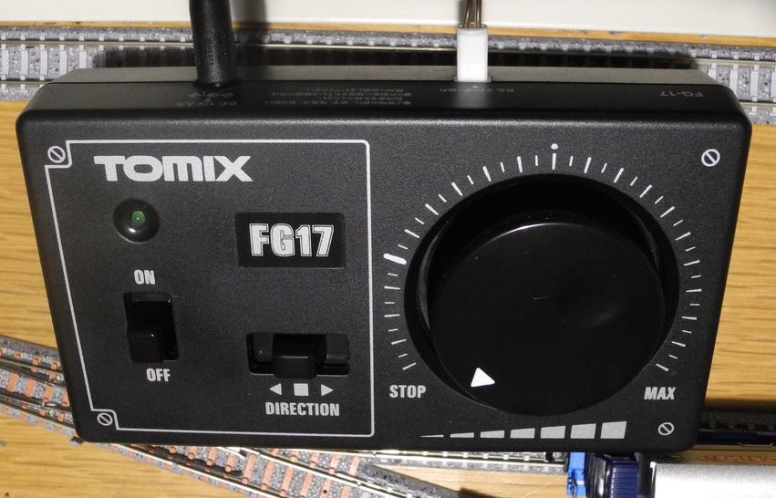 This is the exterior of the budget controller. I have added some white paint into the dial arrow and marked the crawl point. The scale has 20 marks, subdivided, but the potentiometer range goes outside by 1 at Stop and Max.
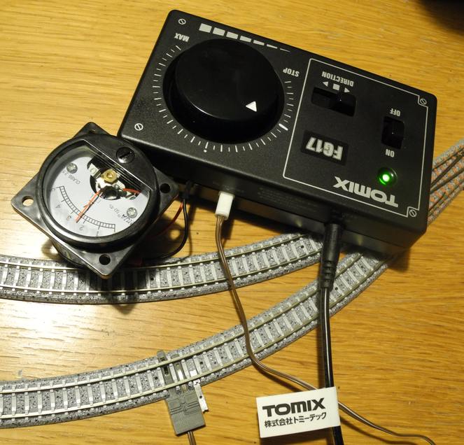 Ah, I actually modified it a bit further, tapping into the power (before the direction switch on the PCB) with a voltmeter, and populated the unused rear bracket with a socket for it. It measures a bit high when the switch is in "pause" mode (which is normally NC but now the voltmeter sits before the NC). It's likely because of low current draw. Regulators and power adapters tend to give inaccurate readings without their natural load. The voltmeter itself only draws 1mA at 5V and 0.5mA at 2.5V so it's not a useful load. Unrelated: the little metal strips dupont connectors come on can be folded and pushed under the rail. I use them for all sorts of things because they're a bit springy.
Ah, by the way, it appears these analog voltmeters can be scaled using a series resistor. There's already a little resistor inside the housing. I later turned this 5V one into a 10V one and repainted the scale.
Ah, I actually modified it a bit further, tapping into the power (before the direction switch on the PCB) with a voltmeter, and populated the unused rear bracket with a socket for it. It measures a bit high when the switch is in "pause" mode (which is normally NC but now the voltmeter sits before the NC). It's likely because of low current draw. Regulators and power adapters tend to give inaccurate readings without their natural load. The voltmeter itself only draws 1mA at 5V and 0.5mA at 2.5V so it's not a useful load. Unrelated: the little metal strips dupont connectors come on can be folded and pushed under the rail. I use them for all sorts of things because they're a bit springy.
Ah, by the way, it appears these analog voltmeters can be scaled using a series resistor. There's already a little resistor inside the housing. I later turned this 5V one into a 10V one and repainted the scale.
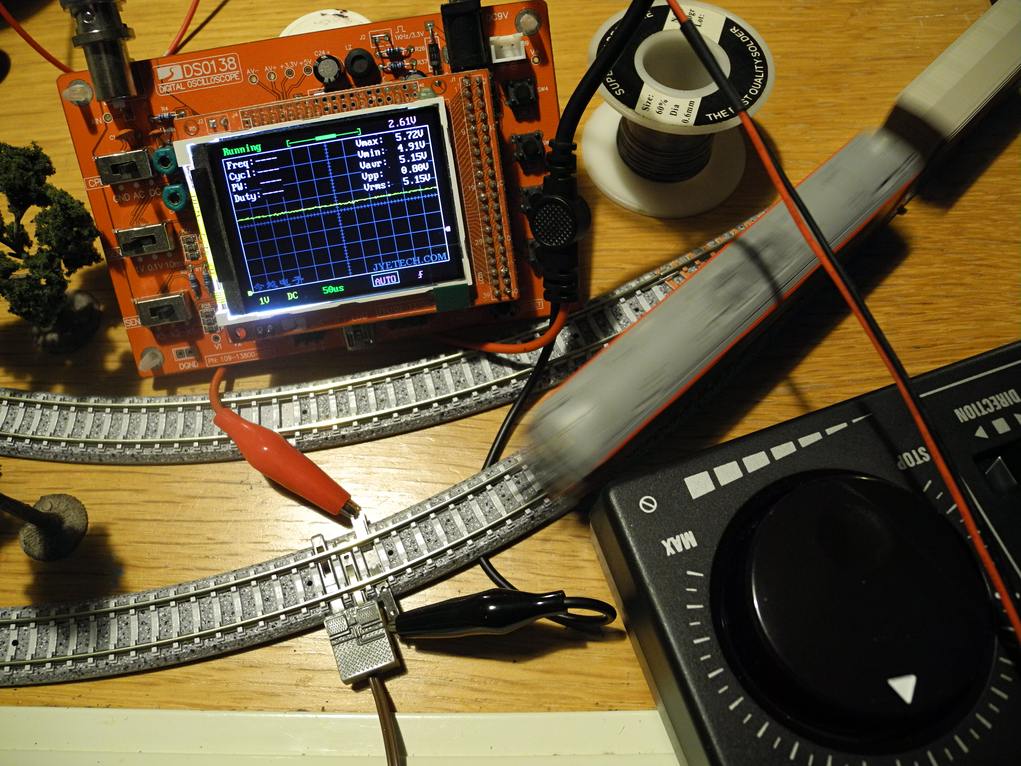 Scoped the rails. Power is pretty steady this close to the feeder. Nothing special going on, like big spikes from the trains. I guess the LM317T is quite stable too. The DSO-cheapo-scope is a bit noisy but I think there was a fix for it...? Setting it to 50us rather than 1ms seems preferable.
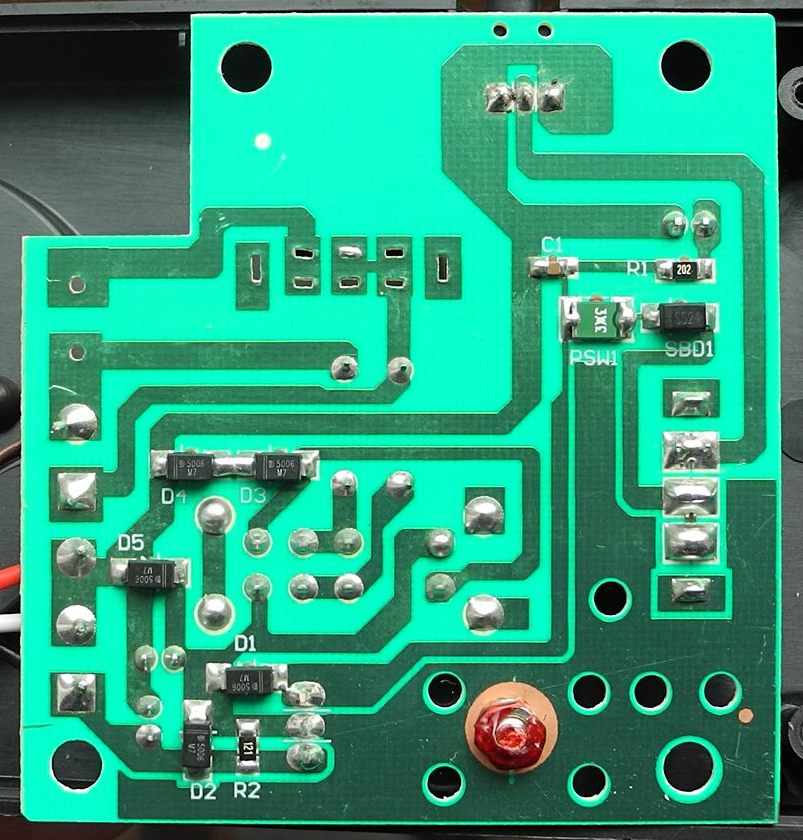 I nearly damaged the diodes on the bottom when I pried the PCB off the screw posts. Here we can see from the pot wires and traces that only the distance from the pot's center pin is used. A larger pot value, the way it's set up against the adjust pin on the LM317T, actually makes the train go faster. The diodes appear to be for protection against various reversing effects. The regulator is bolted down (and locked by red stuff on the nut) through a small heatsink and has a big plane + holes for thermal reasons, though the casing has no vents. There's a green thing near the 12V in jack that I think is a fuse (along with a schottky). The LED gets a 2K resistor because 12V. The tiny ceramic cap is probably for in-power in filtering. There is no big smoothing cap on power to rails... maybe because the LM317T output is already quite steady.
I decided to boot up KiCAD and see if I could make a schematic.
I nearly damaged the diodes on the bottom when I pried the PCB off the screw posts. Here we can see from the pot wires and traces that only the distance from the pot's center pin is used. A larger pot value, the way it's set up against the adjust pin on the LM317T, actually makes the train go faster. The diodes appear to be for protection against various reversing effects. The regulator is bolted down (and locked by red stuff on the nut) through a small heatsink and has a big plane + holes for thermal reasons, though the casing has no vents. There's a green thing near the 12V in jack that I think is a fuse (along with a schottky). The LED gets a 2K resistor because 12V. The tiny ceramic cap is probably for in-power in filtering. There is no big smoothing cap on power to rails... maybe because the LM317T output is already quite steady.
I decided to boot up KiCAD and see if I could make a schematic.
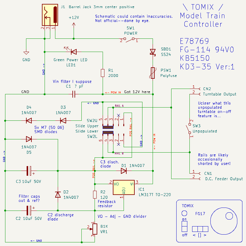 The direction switch is a bit of a mystery on the PCB, but I think it works like this: it has two sides with five points each, and the slider connects three. The center points are always connected via the slider and the rails flip by connecting the center points to the outermost points. The missing pins on the part aren't needed and I think two more could be removed, but three position switches seem to come with pins set up like this.
The configuration around the LM317T IC looks to be fairly standard with D1 and D2 added to protect from the caps misbehaving around the IC. Not sure what the other diodes are for, but a model railroad will definitely experience shorts in play and when fooling around with splits and reverse loops, and they might shield against that.
Normally the LM317T output is minimum 1.25V, but they must have offset that as minimum speed is close to 0V. Maybe it's the diodes or resistor. I wondered about that heatsink on it, and measured its temp, discovering that it went up 7 degrees C while running. Its properties slightly change when warm so maybe that's why the relatively expensive heatsink is there.
Anyways.
The KATO controllers (PWM supposedly) frankly look a bit more interesting visually with the handles and stuff. It wouldn't be impossible to modify the cheap TOMIX controller into something that's immersive though, giving it an analog voltage gauge, speed handle instead of a disc and direction handle instead of the switch, and a row of lit orange indicators like in a KiHa185. Oh, and there must be an alcove for a pocket watch. A cooler flip switch for power. basically taking whatever inspiration is needed from a real train cockpit.
An interesting issue with model railroads is that the model wagons have no breaks and easily roll away even on very subtle slopes, similar to how a marble can roll off a seemingly flat table. This means that any sidetrack / yard will likely have to be perfectly level.
Another model railroad quirk is that rails have resistance, so a train near the supply point will go a bit faster. This means that the track might need to be powered at multiple spots. This can be easily done by just branching out with power wires to a few locations.
It might even be preferable to power sections of rail separately in the case of a modular movable layout. The trains don't really care about the physical solution as long as the current piece of rail they're on is powered. You can drive a train on a single piece of short rail. This is sometimes done in micro-dioramas.
Active track sections can be lit up on a schematic or in the diorama using LEDs. The easiest solution is to use a resistor and two LEDs with one reversed. The brightness of the active direction (rail polarity) LED will vary by the voltage on the rail though, which might be a nice indicator... but constant brightness could be desired in some situations.
I think something like a 358 dual op-amp / comparator (or better, the 393, 339 or 2903) can be used there. The advantage is that it can compare voltages below what would light up an LED, and then output a 5V digital signal which can be used to light up an LED or an inverted one. However, comparing 0V to 0V or floating inputs will likely cause a false indication, so extra logic is needed to turn off the indicator LED at close to zero rail voltage.
Perhaps a MCU is a much better choice for logic stuff and indicators, but I like using silly little chips. Though... If I did use an MCU, I could add a lot of features. I wouldn't have to do a looped track for example. If I put a magnet under a wagon, and a hall effect sensor on the track, then I could perhaps flip the polarity of the tracks using a relay and mosfet/power transistor for PWM speed control. Then I could make a back and forth linear track with timed soft and prolonged stops (to create the illusion of business). An A-B linear layout without a c177 loop takes up less space and can run all trains. This would work better with passenger trains which often have a driver cabin at both ends of the train.
The direction switch is a bit of a mystery on the PCB, but I think it works like this: it has two sides with five points each, and the slider connects three. The center points are always connected via the slider and the rails flip by connecting the center points to the outermost points. The missing pins on the part aren't needed and I think two more could be removed, but three position switches seem to come with pins set up like this.
The configuration around the LM317T IC looks to be fairly standard with D1 and D2 added to protect from the caps misbehaving around the IC. Not sure what the other diodes are for, but a model railroad will definitely experience shorts in play and when fooling around with splits and reverse loops, and they might shield against that.
Normally the LM317T output is minimum 1.25V, but they must have offset that as minimum speed is close to 0V. Maybe it's the diodes or resistor. I wondered about that heatsink on it, and measured its temp, discovering that it went up 7 degrees C while running. Its properties slightly change when warm so maybe that's why the relatively expensive heatsink is there.
Anyways.
The KATO controllers (PWM supposedly) frankly look a bit more interesting visually with the handles and stuff. It wouldn't be impossible to modify the cheap TOMIX controller into something that's immersive though, giving it an analog voltage gauge, speed handle instead of a disc and direction handle instead of the switch, and a row of lit orange indicators like in a KiHa185. Oh, and there must be an alcove for a pocket watch. A cooler flip switch for power. basically taking whatever inspiration is needed from a real train cockpit.
An interesting issue with model railroads is that the model wagons have no breaks and easily roll away even on very subtle slopes, similar to how a marble can roll off a seemingly flat table. This means that any sidetrack / yard will likely have to be perfectly level.
Another model railroad quirk is that rails have resistance, so a train near the supply point will go a bit faster. This means that the track might need to be powered at multiple spots. This can be easily done by just branching out with power wires to a few locations.
It might even be preferable to power sections of rail separately in the case of a modular movable layout. The trains don't really care about the physical solution as long as the current piece of rail they're on is powered. You can drive a train on a single piece of short rail. This is sometimes done in micro-dioramas.
Active track sections can be lit up on a schematic or in the diorama using LEDs. The easiest solution is to use a resistor and two LEDs with one reversed. The brightness of the active direction (rail polarity) LED will vary by the voltage on the rail though, which might be a nice indicator... but constant brightness could be desired in some situations.
I think something like a 358 dual op-amp / comparator (or better, the 393, 339 or 2903) can be used there. The advantage is that it can compare voltages below what would light up an LED, and then output a 5V digital signal which can be used to light up an LED or an inverted one. However, comparing 0V to 0V or floating inputs will likely cause a false indication, so extra logic is needed to turn off the indicator LED at close to zero rail voltage.
Perhaps a MCU is a much better choice for logic stuff and indicators, but I like using silly little chips. Though... If I did use an MCU, I could add a lot of features. I wouldn't have to do a looped track for example. If I put a magnet under a wagon, and a hall effect sensor on the track, then I could perhaps flip the polarity of the tracks using a relay and mosfet/power transistor for PWM speed control. Then I could make a back and forth linear track with timed soft and prolonged stops (to create the illusion of business). An A-B linear layout without a c177 loop takes up less space and can run all trains. This would work better with passenger trains which often have a driver cabin at both ends of the train.
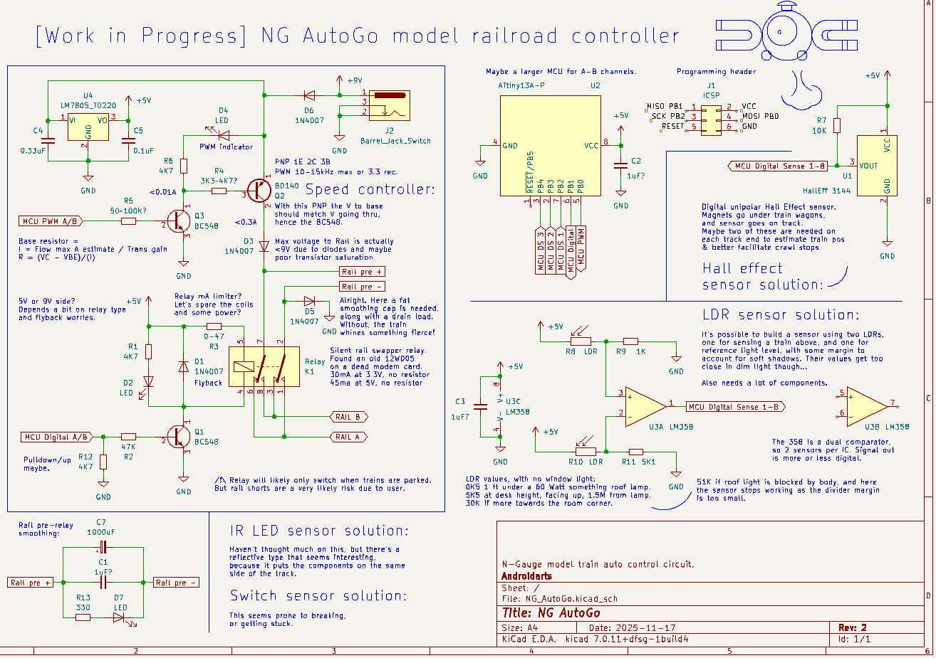 Had a go at it and made a schematic in KiCAD. There are more than one way to make a sensor...
As for the relay, I believe I got it off a dead 56 modem or PC card. It's a 12WD05 Relay from 1999, but I plan to get some more modern ones. The BD140 is just something I had laying about. I have a tendency of turning Mosfets into resistors so I avoided them this time.
I don't think I'll make a PCB design for a one-off experimental design like this, rather—because railroads are such an oldschool hobby—I might actually breadboard this. Breadboard as in using a physical wooden board with nails, and not the plastic ones with holes (so intermittent and noisy!) or the perf board blank PCBs. Just make a wooden slab.
As a sidenote, ATmega328P's Timer1 PWM (using AnalogWrite on pin 10) (...and the Arduino IDE) is 490Hz according to my multimeter. By changing the TCCR1B to binary 10, a prescaler is lowered to 8 from 64, giving a 3.9KHz speed. I don't know what works best with trains, but if a LED PWM is visible to the naked eye it can proably also be heard and seen on trains. The BD140 switching speed is limited to the KHz range from what I read. There are better options than the BD140 really, but the package is so nice.
After testing this system with a 555 timer it sort of worked but the slow pulse made the train stutter. So I hooked up the MCU, and the train just beeped! Wouldn't go. Coil whine? Well, I hadn't put a cap on the rails for smoothing. But even with that it whined a bit at low duty/speed. I tested both 490Hz and 3.9Khz... the latter beeped worse and didn't serve to smooth the voltage. Additionally, without a load on the track, the voltmeter just slamed between 0 and max voltage. The beeping problem went away when I brought out a beefy 1000uF and placed it across the rails, along with the probably meaningless 105 ceramic. I guess I need a LED load to help drain that cap so it doesn't sit charged if the train is lifted.
The PWM is not quite linear in how it translates to speed. Looks like the lower speeds must be transitioned more gently for the train start and stop creeping to look natural. I can't see much difference between the higher speeds.
The temp of the naked BD140 only goes up a some 5 degrees. I don't think I'm taxing it that hard. It does seem to whine a bit when the PWM is low and the train is struggling to move. I thought only coils whined.
Had a go at it and made a schematic in KiCAD. There are more than one way to make a sensor...
As for the relay, I believe I got it off a dead 56 modem or PC card. It's a 12WD05 Relay from 1999, but I plan to get some more modern ones. The BD140 is just something I had laying about. I have a tendency of turning Mosfets into resistors so I avoided them this time.
I don't think I'll make a PCB design for a one-off experimental design like this, rather—because railroads are such an oldschool hobby—I might actually breadboard this. Breadboard as in using a physical wooden board with nails, and not the plastic ones with holes (so intermittent and noisy!) or the perf board blank PCBs. Just make a wooden slab.
As a sidenote, ATmega328P's Timer1 PWM (using AnalogWrite on pin 10) (...and the Arduino IDE) is 490Hz according to my multimeter. By changing the TCCR1B to binary 10, a prescaler is lowered to 8 from 64, giving a 3.9KHz speed. I don't know what works best with trains, but if a LED PWM is visible to the naked eye it can proably also be heard and seen on trains. The BD140 switching speed is limited to the KHz range from what I read. There are better options than the BD140 really, but the package is so nice.
After testing this system with a 555 timer it sort of worked but the slow pulse made the train stutter. So I hooked up the MCU, and the train just beeped! Wouldn't go. Coil whine? Well, I hadn't put a cap on the rails for smoothing. But even with that it whined a bit at low duty/speed. I tested both 490Hz and 3.9Khz... the latter beeped worse and didn't serve to smooth the voltage. Additionally, without a load on the track, the voltmeter just slamed between 0 and max voltage. The beeping problem went away when I brought out a beefy 1000uF and placed it across the rails, along with the probably meaningless 105 ceramic. I guess I need a LED load to help drain that cap so it doesn't sit charged if the train is lifted.
The PWM is not quite linear in how it translates to speed. Looks like the lower speeds must be transitioned more gently for the train start and stop creeping to look natural. I can't see much difference between the higher speeds.
The temp of the naked BD140 only goes up a some 5 degrees. I don't think I'm taxing it that hard. It does seem to whine a bit when the PWM is low and the train is struggling to move. I thought only coils whined.
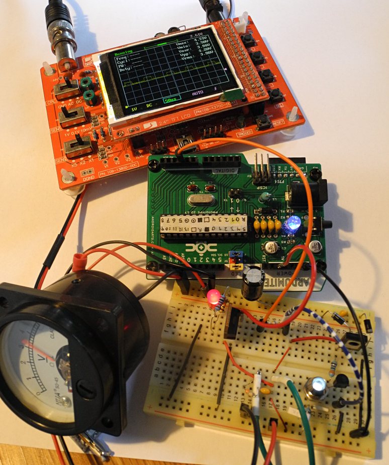 Brought out the scope again. The MCU is hooked up and pulsing (it's my own Ardumite PCB). With a 5V regulator needed for the MCU, the in voltage should be 7-9V for the BD140 train transistor to be able to do useful work with all the diode drops and stuff. Also and the BD140 might not be fully saturated with my resistor values ...or maybe it is—I fiddled with the resistor values on both transistors and didn't notice a lot of difference in speed or throughput voltage.
I didn't tweak the smoothing/filtering so there's still some squarewaves on power, visible on the scope. Not audible to me though.
There's no train stutter due to PWM as it's 3.9KHz. But... uh, macro stuttering (or jerking) is something both trains do, even on perfectly steady power. Could be a conductivity degradation issue that emerges due to dirt / oxidation. The tracks really do get black quite quickly. Stuttering and even freezes tends to happen more often at the splits ("frogs") where there are some track gaps.
Anyways, after I got all this transistor driving working, I discovered that when I swap out the DF200 for the DE10 then I need a whole new profile for acceleration. Also, if I put two trains on the track, then there's some sort of supply issue and they barely run. A power transistor is kind of set up for a specific load I guess? Boo.
Tried getting rid of the residual PWM noise with a pi lowpass filter but no dice.
Brought out the scope again. The MCU is hooked up and pulsing (it's my own Ardumite PCB). With a 5V regulator needed for the MCU, the in voltage should be 7-9V for the BD140 train transistor to be able to do useful work with all the diode drops and stuff. Also and the BD140 might not be fully saturated with my resistor values ...or maybe it is—I fiddled with the resistor values on both transistors and didn't notice a lot of difference in speed or throughput voltage.
I didn't tweak the smoothing/filtering so there's still some squarewaves on power, visible on the scope. Not audible to me though.
There's no train stutter due to PWM as it's 3.9KHz. But... uh, macro stuttering (or jerking) is something both trains do, even on perfectly steady power. Could be a conductivity degradation issue that emerges due to dirt / oxidation. The tracks really do get black quite quickly. Stuttering and even freezes tends to happen more often at the splits ("frogs") where there are some track gaps.
Anyways, after I got all this transistor driving working, I discovered that when I swap out the DF200 for the DE10 then I need a whole new profile for acceleration. Also, if I put two trains on the track, then there's some sort of supply issue and they barely run. A power transistor is kind of set up for a specific load I guess? Boo.
Tried getting rid of the residual PWM noise with a pi lowpass filter but no dice.
Sidetracked by an Idea
As for a homemade remote solution for the track switcher, making coils is too difficult. Perhaps marionette strings would work? There are some convenient gaps inside the track part that one can thread strings through, then noose them around the knob. When the track is mounted the string can go down under the diorama board and be guided over to a rotary knob that pulls it. This solution is not practical for temp setups on a table though, and it appears friction and stretching is an issue.
The Trains
The trains are powered through the rail, going up the metal wheels, which are not a single piece as that would short across the rails. A screw motor transfers rotation down the the wheels. One of the wheels have a coating for traction as metal on metal would slip. Because of the cogs, trains won't roll and are safe to park anywhere. I noticed that even the cheap wagons I got also have metal wheels, and also metal weights hidden in the cargo or carriage. Most trains seem to have light-up effects. It's quite easy to light up anything sitting on powered rail, but one might need two LEDs to account for polarity, or a full bridge rectifier. A smoothing cap might also be needed as on lower speeds the lights will flicker. With voltage being variable the LED brightness will also vary, though it's possible to regulate I suppose. They just won't come on at lower speeds, but then again, the train doesn't move at low voltages either.
Model Mini Physics
The docking knuckles are designed to connect when bumped together. There are a few variants which look more realistic, but perform worse at model scale. Also, curvature has to be considered. In real life you want to build very flat and very straight rail. Trains are not good uphill and downhill, since they rely on low friction rolling (they have to break going downhill and can't just madly cruise). Curves are very gentle in real life (over 1m in radius at 1:150), but on a model railroad space is very limited and curves are tighter. Not all model trains and wagons can take the tightest curves available due to how the wheel sections are placed and how they rotate, and the wagon-wagon connections can also be twisted out too far, causing derailments or dropped wagons. Even when long wagons can handle tight curves it looks very unnatural and polygonal.
When putting the models onto the rail, the wedge thing helps immensely. It can be done without if one is up close, but model railroads often require reaching in quite far, and some wagons have tons of little wiggly wheels that need to be aligned with sub-millimetre precision.
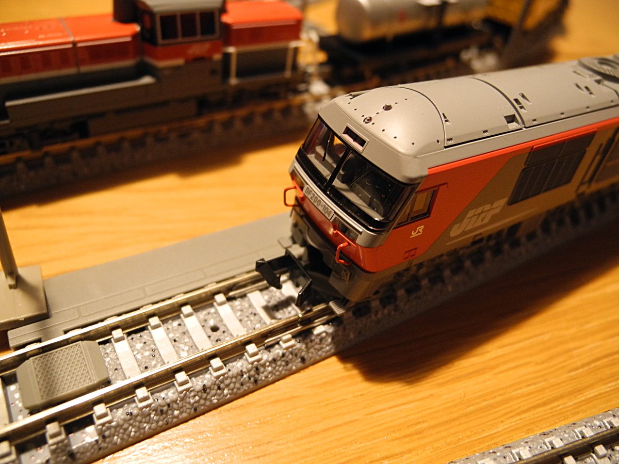 Like I said earlier, the models at this scale are fairly fragile. I have a DE10 (KATO 7011-3) with little handrails and I can only pick it up holding a certain spot. The TOMIX DF200 seen above comes with the most brittle little plastic front thingies I have ever seen in a kit, and I made my own using metal resistor legs instead (painted red).
The KATO DE10 impressed me with some very elaborate multiface moulding, spray painting, and silvery pad printing for the serial number placard sprues.
I noticed that the TOMIX DF200 does way better on the low power of the beginner kit than the KATO DE10 (which I'm unable to start at a crawl, though slowing it down to it works... this being DC power, not PWM which KATO trains are supposedly be tuned for, but I think with smoothing there's no such thing as PWM, because it would be audible as my failure showed).
My KATO DE10 sometimes makes a whirring noise that goes away after a while. It's not as fun to drive as the TOMIX DF200.
Like I said earlier, the models at this scale are fairly fragile. I have a DE10 (KATO 7011-3) with little handrails and I can only pick it up holding a certain spot. The TOMIX DF200 seen above comes with the most brittle little plastic front thingies I have ever seen in a kit, and I made my own using metal resistor legs instead (painted red).
The KATO DE10 impressed me with some very elaborate multiface moulding, spray painting, and silvery pad printing for the serial number placard sprues.
I noticed that the TOMIX DF200 does way better on the low power of the beginner kit than the KATO DE10 (which I'm unable to start at a crawl, though slowing it down to it works... this being DC power, not PWM which KATO trains are supposedly be tuned for, but I think with smoothing there's no such thing as PWM, because it would be audible as my failure showed).
My KATO DE10 sometimes makes a whirring noise that goes away after a while. It's not as fun to drive as the TOMIX DF200.
Beginner Thoughts
There are a few predominant types of railway layouts being showcased online by hobbyists.
First, there's the loop with some sidetracks. There are not very immersive as the train isn't really going anywhere and looping rail is not a thing in real life. However, this type of layout can still be relaxing to watch. It can be developed with a side track for parking or parallel action. It can also be squished into a sort of dogbone shape (running along a wall or table) so it looks like the train is going between two town or industries. By hiding the train behind a tunnel, the illusion of distance can be enhanced further.
Then there's the diorama. These can be a tiny loop or just a short stretch of rail. It's more of a way to display a scene. Sometimes dioramas are modular, and people connect a bunch together at a hobby convention.
Finally, the largest layouts are built by the generation who could afford to buy a house with a large basement or garage. There are usually large long rail yards for parking and logistics. I don't have space, time or money for anything like that. The electrical work also becomes more complex and while I could handle it, mega-layouts are not really my jazz.
So my idea was to get a bit of this and that for a few hundred euro tops, and try to build a small layout with a loop and a few side tracks. One mistake I made was that I bought a few boxes with starter stuff, but these sets didn't really contain exactly what I needed, and the wagons I sampled are too much of a mish-mash when stringed along.
So my recommendations to my past self are:
Don't over-complicate the first layout with grand plans. Scale it down.
Only buy the trains you really want. The DF200 was nice, but it's not my favourite visually, though it runs quite nice (can barely handle c177 though due to its center bogie).
Freight trains are more complicated to run because of the wagon logistics and directionality. A two-part passenger train like the Kiara doesn't have a clear front and costs less overall.
The railyard house set was also nice, but too expensive compared to getting the exact things I needed, and the neat interior is also hidden unless one takes the roof off.
The wagons are not expensive, but with my random assortment, pulling anything more than two or three looks very strange. But I don't want to go all in and buy a set of 8 identical wagons that I'll likely grow bored of seeing, so maybe I made the right choice after all. Also, with a smaller layout and shorter side track, a string of 8 wagons won't fit.
On Track
It's possible to modify the track pieces by sawing them off, but it's not possible to bend them (though some manufacturers make flexible track). Even if a piece is shortened to complete a loop nicely, there's a good chance the completed curve won't be smooth.
(Sawing off will break continuity, which can be fixed by soldering or just adding another point of power. The trains only care about power on the rail underneath and can even run standing on a single piece. In some cases one might want to break the circuit deliberately to solve polarity issues resulting from the track looping in a "forbidden" way which flips the train, e.g. a sewing needle / balloon on a string shape.)
Because of the aforementioned curvature issues, it's best to get a variety of different curve radii. I got eight c280 45 in my TOMIX starter set. c280 means the radius from center track to loop center is 280mm. 45 is degrees, and 8x45 is 360.
Loose pieces are often sold in packs of four, and 15, 30 and 45 degree "lengths". The shorter 15 degree pieces are good for adjusting or patching up places. Since the splits (points) turn out 15 degrees, a 15 degree piece will also bring the track back in parallel. The radius here determines the spacing of the two parallel tracks, and the station kits are made for certain spacings. A large radius piece will bring the tracks further apart. Since a split to parallel will produce two tracks, the lengths of these must now match. Without a supply of various short pieces, I fear the saw will have to come out.
As for cutting track, perhaps it has to be done at the middle, patching it back up so there are still connections on each end. Soldering isn't strictly needed but can help to smooth out the rail. IIRC, soft solder can be whittled with a knife in case there's a bump. Plastic structural support can be put underneath. In the end, the track might be nailed or glued onto the diorama board though—tracks can bow up slightly when just put on a table I've noticed.
The c280 curve radius might work well for others, but proved too large for the space I have available so going down to c243 or c177 is a must... getting that starter set was a bit of a waste, perhaps. Not all trains and wagons can take the "mini" curves though... which means I have to go through lists and reviews. I have some 50cm available for the turn, and a c177 180 degree turn doubles to 34.5cm, but obviously needs margin for the terrain and safety.
There are some neat pieces with a cant (lean). In real life, modern trains lean inward in the curves. Some high speed stretches of rail leans, and I think the trains have hydraulics or something for it, and possibly it also happens due to the shape of their conical wheels being displaced sideways.
There are track piece stencil templates available for drafting layouts on a drawing board, but a person savvy with computers can easily produce their own digital track tiles. I just printed out the product image of the stencil they sell, and made my own paper model. A little late I found not one, but two circle stencils in a drawer. These somewhat work at a 1:1 scale, but 177mm would have to become 18mm, or 35 in the case of diameter.
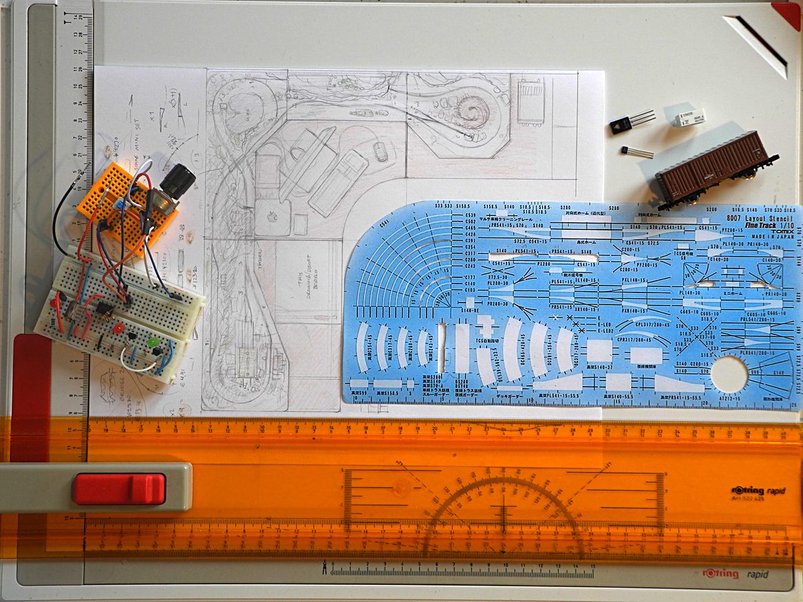 ( Also pictured some components I might use, and an abandoned idea for constant-brightness polarity indicators using transistors and a 358 op-amp in comparator mode. The DPDT toggle switch is for rail swapping and pot is a voltage divider. Turns out comparing with voltage at its lowest gives a false indication. )
The track packs aren't expensive at 10€ or less for 4 tracks, but the splits are almost 20 each for the manual ones (I found that even though the Yen is currently weak, shipping, local VAT and customs fully negate this). To build anything a bit more substantial like a dogbone loop, I think one would need the 180 degree ends, straight rail, a few variants of the 15 degree rail, and three splits to make it a bit more engaging. Maybe 125€ total for tracks. A few buildings at 15€ each, then a 50€ train, 5x 5€ simple wagons, so another 125. Finally a controller is needed unless you can build your own variable power supply with the necessary safety precautions (needed since the track is exposed and there's a lot of noise and changing polarity).
I think the KATO "Standard SX" device looks way nicer than the TOMIX ones. More immersive. It probably works with TOMIX tracks and feeder (track connection) wire with some modification. Or straight-up with the KATO tracks of course.
My TOMIX set came with a small 500mA AC adaptor, but I could have built my own I suppose. It's just 12V DC out to a 3mm jack. The barrel jack on the KATO controller seems like it's a larger variant and their loose AC adaptors look quite beefy (more milliamps I guess).
Anyways, maybe 300€ total to get started (almost half if one could teleport things from Japan). The DF200 "First Set" I got was a bit under 10000 Yen—just 50€ with the teleporter, but 100€ the way I'm counting here. It came with a full c280 loop (two c280 45 packs), spaced by two straights (half a s280 pack), then a train and container wagon, the controller*, AC adaptor, and the handy wedge for getting the models on track. Rather good value, but only if you're gonna use any of it.
* Technically—if you're handy but poor—you can make your own adjustable power supply using scavenged power adaptors, regulators, diodes, potentiometers and DPDT switches / relays. The trains kind of just need 0-9 Volts.
I haven't mentioned terrain making, but it's another cost. I guess one would need flock for trees and grass (can be DIY though from yarn and cork), wood glue, plaster of Paris, structural boards and other building materials. Another approach is to not build anything permanently and got for a wargaming approach, with a mat and loose terrain pieces, and a dynamic layout. That's probably easier to clean too.
( Also pictured some components I might use, and an abandoned idea for constant-brightness polarity indicators using transistors and a 358 op-amp in comparator mode. The DPDT toggle switch is for rail swapping and pot is a voltage divider. Turns out comparing with voltage at its lowest gives a false indication. )
The track packs aren't expensive at 10€ or less for 4 tracks, but the splits are almost 20 each for the manual ones (I found that even though the Yen is currently weak, shipping, local VAT and customs fully negate this). To build anything a bit more substantial like a dogbone loop, I think one would need the 180 degree ends, straight rail, a few variants of the 15 degree rail, and three splits to make it a bit more engaging. Maybe 125€ total for tracks. A few buildings at 15€ each, then a 50€ train, 5x 5€ simple wagons, so another 125. Finally a controller is needed unless you can build your own variable power supply with the necessary safety precautions (needed since the track is exposed and there's a lot of noise and changing polarity).
I think the KATO "Standard SX" device looks way nicer than the TOMIX ones. More immersive. It probably works with TOMIX tracks and feeder (track connection) wire with some modification. Or straight-up with the KATO tracks of course.
My TOMIX set came with a small 500mA AC adaptor, but I could have built my own I suppose. It's just 12V DC out to a 3mm jack. The barrel jack on the KATO controller seems like it's a larger variant and their loose AC adaptors look quite beefy (more milliamps I guess).
Anyways, maybe 300€ total to get started (almost half if one could teleport things from Japan). The DF200 "First Set" I got was a bit under 10000 Yen—just 50€ with the teleporter, but 100€ the way I'm counting here. It came with a full c280 loop (two c280 45 packs), spaced by two straights (half a s280 pack), then a train and container wagon, the controller*, AC adaptor, and the handy wedge for getting the models on track. Rather good value, but only if you're gonna use any of it.
* Technically—if you're handy but poor—you can make your own adjustable power supply using scavenged power adaptors, regulators, diodes, potentiometers and DPDT switches / relays. The trains kind of just need 0-9 Volts.
I haven't mentioned terrain making, but it's another cost. I guess one would need flock for trees and grass (can be DIY though from yarn and cork), wood glue, plaster of Paris, structural boards and other building materials. Another approach is to not build anything permanently and got for a wargaming approach, with a mat and loose terrain pieces, and a dynamic layout. That's probably easier to clean too.
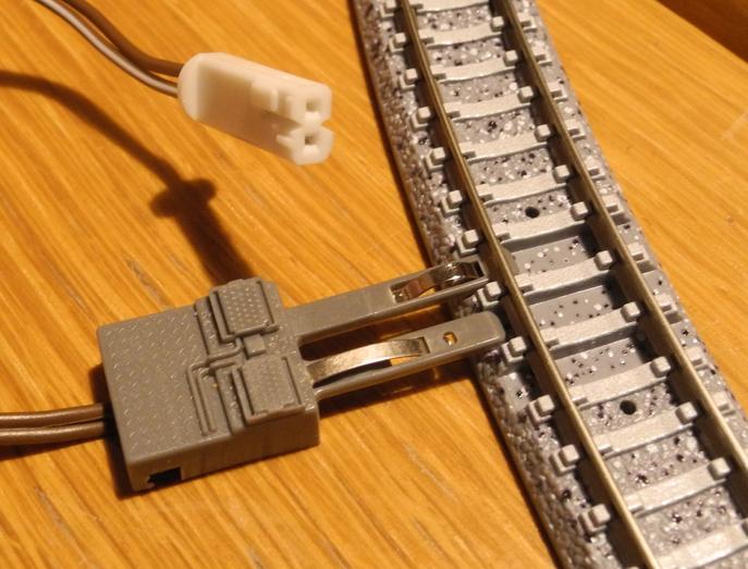 D.C. Feeder system. Pushes in under the rail in three special dips that each track piece has. Insert the feeder from the other side of the rail and polarity/direction switches. The white plug goes into the controller, and is subtly keyed... not sure why, but perhaps polarity matters for some peripherals. If needed, I suppose the key can be shaved off when it comes to the rail feeder.
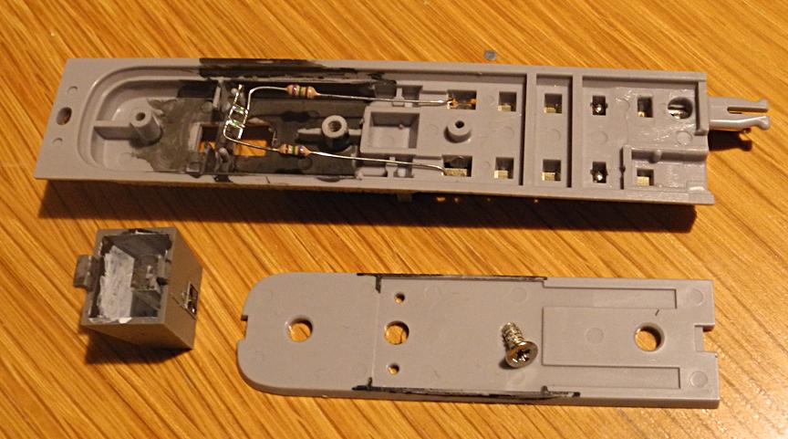 I suspect a light-up PCB is sold with these rail ends. I made my own using some resistors and SMD LEDs 69-ing. Deadbugged them on a tape to hold them in place while soldering. Two are needed since polarity is unknown. If a different colour, they can indicate direction, like entering or leaving the stop. Similar to the train lights they are not constant brightness and will turn off at lower voltages. The light will leak through the plastic so I painted it inside.
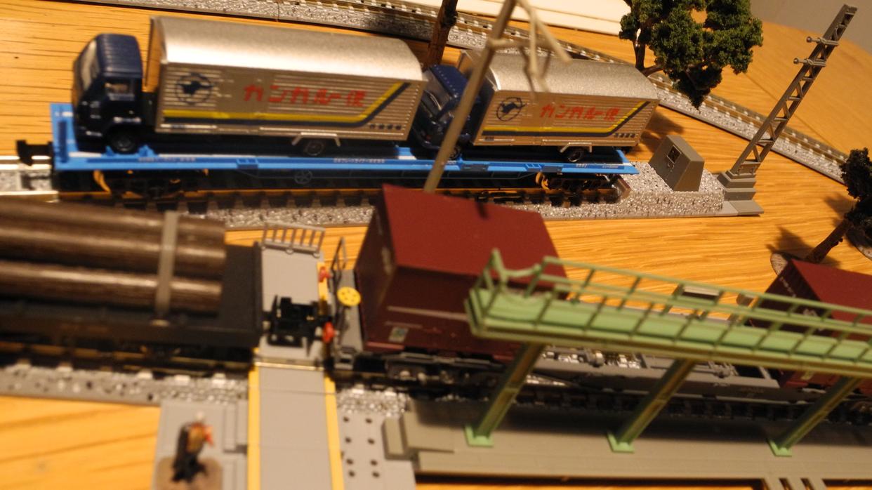 Some decals applied. The stop (not lit here) and parts of the rail yard set. Can you spot Char?
Fine Details
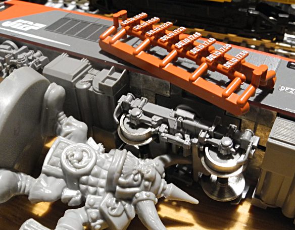 Yeah, there are a lot of details on these models (blurry pic—local light a bit too dim for my camera's shutter here). Old plastic Ork for scale! Also, look at that registration number options sprue that came with the KATO DE10. Not only is it spray painted, but it has silver lettering too. And that's a multi-face mould. The TOMIX DF200 number sprue was much simpler.
Weathering
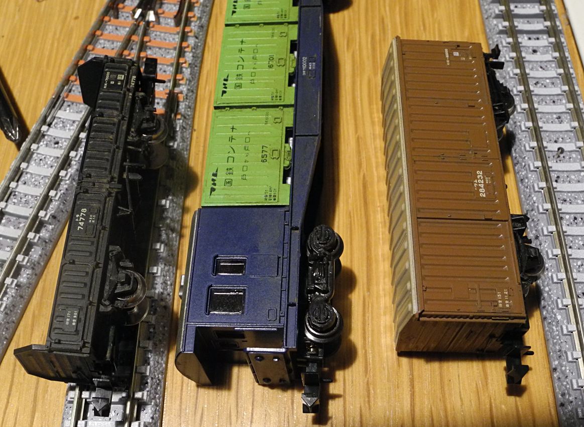 A mostly reversible weathering technique I've developed uses watercolours—the cheap ones for kids with larger pigment that dries really dull/dusty. While it doesn't stick super well to gloss plastic, it kind of does after a second pass. It helps to use a sponge, and putting some surface-tension breaking media in the water. After drying it becomes a lot lighter and might look odd if it pooled into some corners, but it's easy to adjust the weathering since it's just water colour. Also, even if very subtle, the scattered pigment particles will reduce the overall glossiness of the plastic. I primarily use colours like black for depth, brown, sienna, hot orange for rust, and gray for muted areas.
( I discovered right after doing this that scraping pigment off Faber-Castell artists chalky sticks works even better than water colour as the pigment is finer but still dries dull. )
A dusty band going along the entire line can tie it together a bit, whereas sticking to the naked plastic makes everything seem a bit disparate.
Trains don't have much copper on them, but a teal (blue+green) can be used to weather copper.
Weathering the rails rusty using black and hot orange might be doable... not sure. There are special pens for it I think. But I'd rather glue down ballast before going there. I think the ballast at railyards often gets tinted a satin dark oily colour. The top of the rails should be kept a polished metal of course.
A mostly reversible weathering technique I've developed uses watercolours—the cheap ones for kids with larger pigment that dries really dull/dusty. While it doesn't stick super well to gloss plastic, it kind of does after a second pass. It helps to use a sponge, and putting some surface-tension breaking media in the water. After drying it becomes a lot lighter and might look odd if it pooled into some corners, but it's easy to adjust the weathering since it's just water colour. Also, even if very subtle, the scattered pigment particles will reduce the overall glossiness of the plastic. I primarily use colours like black for depth, brown, sienna, hot orange for rust, and gray for muted areas.
( I discovered right after doing this that scraping pigment off Faber-Castell artists chalky sticks works even better than water colour as the pigment is finer but still dries dull. )
A dusty band going along the entire line can tie it together a bit, whereas sticking to the naked plastic makes everything seem a bit disparate.
Trains don't have much copper on them, but a teal (blue+green) can be used to weather copper.
Weathering the rails rusty using black and hot orange might be doable... not sure. There are special pens for it I think. But I'd rather glue down ballast before going there. I think the ballast at railyards often gets tinted a satin dark oily colour. The top of the rails should be kept a polished metal of course.
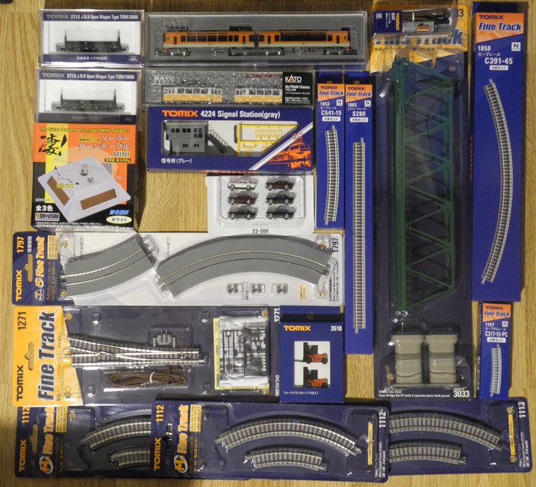 Another haul. Thought those were HO scale forklifts at first, but they are container forklifts, Mitsubishi FD300s I believe. KATO My Tram and Kiara. The very short pieces are not as economical as long pieces, but come in handy when patching up the last stretch when layouting, or when a slight angle change is needed.
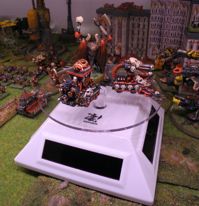 The Doyusha solar turntable was cheap and I thought I understood why right away—it made a terrible ruckus when spinning. Was gonna warn about it, but decided to instead open it up. The problem was the magnet cog wheel bumping into the coil and black posts, which I fixed by shaving off some plastic. It now spins somewhat silently when placed one foot from a 40W bulb. At slower speeds it's more silent.
When powered by an old AA battery it draws a mere 130uA at 1V, but this is with some additional fractional power from the solar panels (in a lit room). Basically an old battery can be used to boost the solar panels in weak light (battery sits in parallel, not series). When powered from my bench PSU at 1.5V it draws 230uA. At 2V it's 330uA. At 1.25V it's 160uA. Since an AA battery holds between 500-2500mAh depending on type, this yields... half a year of operation? Really? Is that how it works?
With boosted with a "used" 1V battery in a lit room the plate does spin a little fast and might need a resistor. A 4K7, 5K1, 6K8 will bring it down to the slowest speed (and around 50uA). That's approaching an MCU in sleep mode. A little 10K (103) trimpot might be a good choice as with a full 1.5V battery more Ohms are needed to slow the plate. In a dark shelf closer to zero Ohm is better. It's tricky to add a resistor into the circuit without taking out the PCB and cutting a trace because of the battery compartment construction.
The Doyusha solar turntable was cheap and I thought I understood why right away—it made a terrible ruckus when spinning. Was gonna warn about it, but decided to instead open it up. The problem was the magnet cog wheel bumping into the coil and black posts, which I fixed by shaving off some plastic. It now spins somewhat silently when placed one foot from a 40W bulb. At slower speeds it's more silent.
When powered by an old AA battery it draws a mere 130uA at 1V, but this is with some additional fractional power from the solar panels (in a lit room). Basically an old battery can be used to boost the solar panels in weak light (battery sits in parallel, not series). When powered from my bench PSU at 1.5V it draws 230uA. At 2V it's 330uA. At 1.25V it's 160uA. Since an AA battery holds between 500-2500mAh depending on type, this yields... half a year of operation? Really? Is that how it works?
With boosted with a "used" 1V battery in a lit room the plate does spin a little fast and might need a resistor. A 4K7, 5K1, 6K8 will bring it down to the slowest speed (and around 50uA). That's approaching an MCU in sleep mode. A little 10K (103) trimpot might be a good choice as with a full 1.5V battery more Ohms are needed to slow the plate. In a dark shelf closer to zero Ohm is better. It's tricky to add a resistor into the circuit without taking out the PCB and cutting a trace because of the battery compartment construction.
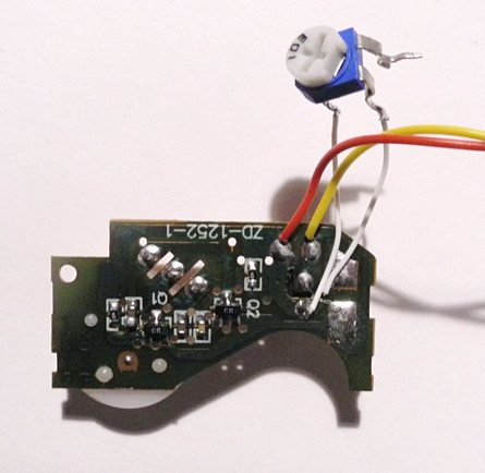
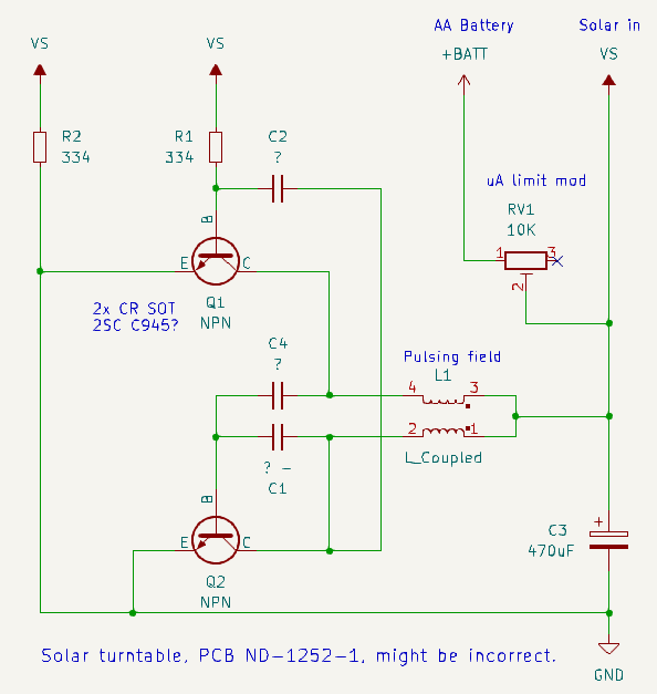 The best place to add a resistor. The circuit looks like it might be a flipflop oscillator (a variant of the astable multivibrator) with those two "CR" NPNs and B-C caps. 470uF bulk cap at power input. Three poles on the coil (looks like two joined to power, and each end going to a SOT transistor). The plate can rotate in any direction as the coil pulse is just a pulse that puts the magnet flywheel in motion.
This particular construction with a coil that spins up a magnet wheel is used in wall timers, though there the AC waveform is used to pulse the coil afaik.
The best place to add a resistor. The circuit looks like it might be a flipflop oscillator (a variant of the astable multivibrator) with those two "CR" NPNs and B-C caps. 470uF bulk cap at power input. Three poles on the coil (looks like two joined to power, and each end going to a SOT transistor). The plate can rotate in any direction as the coil pulse is just a pulse that puts the magnet flywheel in motion.
This particular construction with a coil that spins up a magnet wheel is used in wall timers, though there the AC waveform is used to pulse the coil afaik.
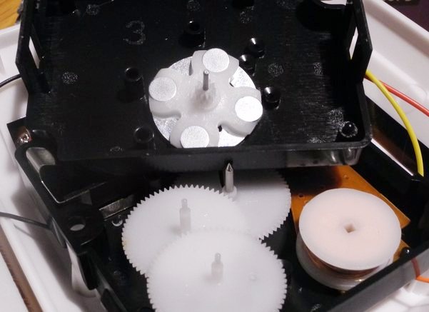 The magnet wheel plastic holder that might need trimming. Or was it the black posts causing trouble? Unsure.
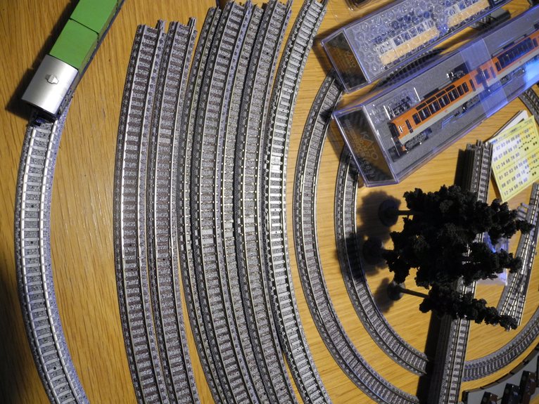 Various radii and angle curves, assembled. c140 and c177 at center.
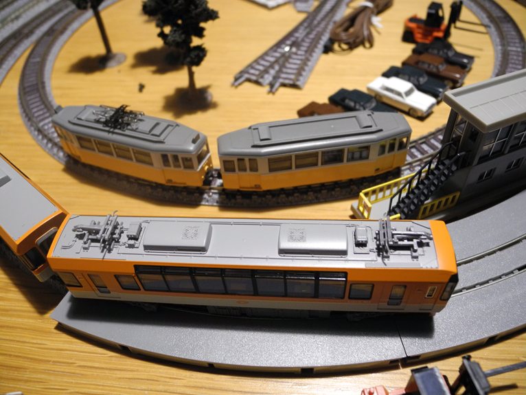 Two new trains running in the mini curves. KATO Kiara (c177 curve ) and My Tram (c140 curve).
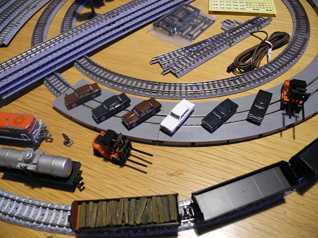 1980s Toyotas. Cressida? Corolla? No, it's the Crown. The tires, license plates and headlights need painting. Pretty good mould detail.
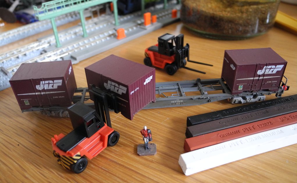 These Faber Castell sticks have fine pigments that—if scraped off with a knife—work better than water colour for weathering.
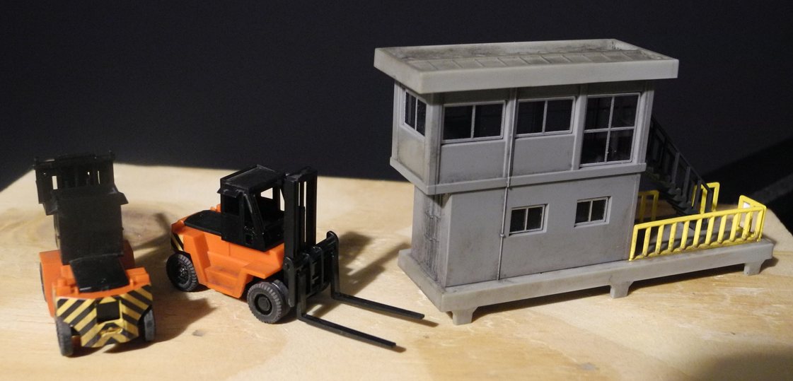 Weathered the forklifts and the building. The building has a bottom hole for lighting. Haven't painted the building rims here (the kit came with stickers for it). The FD300 forklifts are missing some fine detail like steps up to the cabin door. And print.
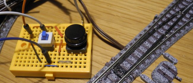 I didn't the control/dashboard switches for the "points", so I built this using a DPDT toggle switch and a momentary button. 8-9V is enough for the coils to work, but my bench PSU detects it as a short because the coil Ohm rather low. Not sure if a resistor is used in the official designs. A DPDT flip-switch is visually more useful than the one I used here.
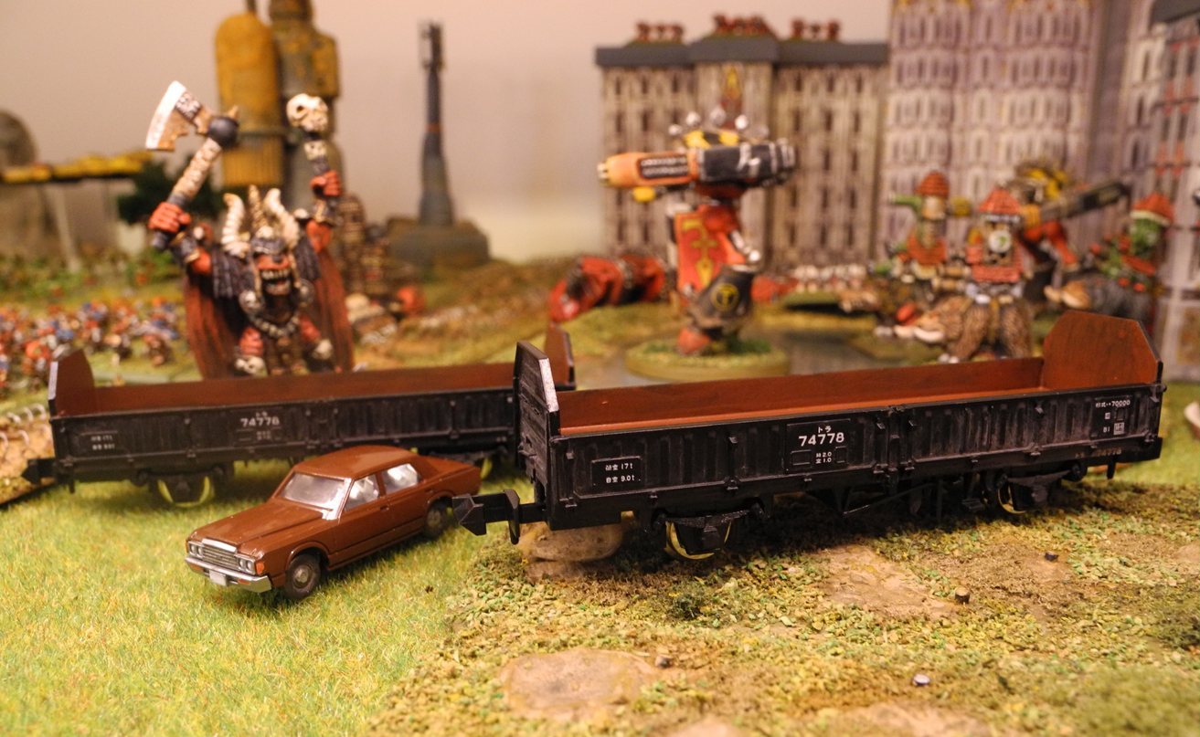 Two more ToRa 70000, with weathering. And a painted Toyota.
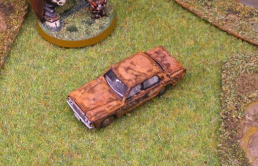 Rusty car. Mix of Faber Castell sticks and water colour orange.
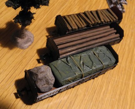 Stick cargo.